Friday, December 21, 2012

Android App for Photographers

I had found out recently that my mom had an old 35mm SLR, with some really great lenses, that I didn't know about. Since she wasn't using it she let me borrow it. 

Thanks Mom
One problem I had was what should I set the film speed too? 

Usually a digital camera would just do this for me

Well I found a nifty equation that relates ISO speed, aperture, luminance and exposure time on Wikipedia. 


Where N is the aperture (f-stops), L is luminance (lux), S is the film speed (ISO) t is the exposure time (seconds) and K is a constant (14 for Pentax cameras). 

I could find N, K and S fairly easily as they were given, but what about L? I didn't have a lux meter lying around. But, I did have an Android device with a light sensor and found out there were free lux meter apps

But the apps had adds in them! 

Then I found out that it was a pretty trivial excise to get light sensor data and print it to the screen. Since Google has made the Android app development environment pretty open all I had to do was fire up my Eclipse IDE and make my own lux meter app. 

And I did, but why stop there? Since I eventually wanted to calculate the ideal exposure time for a scene and I didn't really want to do the calculations every time I wanted to take a shot, I decided to extend my app to let me input aperture, film speed and the calibration constant and my phone would detect the luminance and calculate the exposure time for me. 

It took me about an evening to relearn the Android API and implement that well defined functionality. 

Pretty cool huh?
I put a large button on the bottom to let the user press to sample the luminance because most light sensors are on the face of the device, which means that the user must point the screen away from them to sample the luminance from their subject. A really big button would let them press somewhere on the bottom of their screen to do that. 

I decided at this point to actually make this an actual app at this point. Which meant designing a logo. And I, of course, chose a camera diaphragm for the logo because nothing says photography like a diaphragm. 

Surprisingly it took more math to design the logo than the app actually used. 

I swear these are not satanic symbols
Once I mapped all the coordinates for all the triangles in the diaphragm I wrote the image in an SVG file and rasterized it to a png. 

It's like the logo of some '60s Bond villan's criminal organization
At this point I had to think about licensing, since this was a pretty trivial app I'm sure there is a lot that could be done to improve it, so I decided to license it under the GNU General Public License to ensure that it would always exist to let people use it how they want and modify it to fit their needs. 

One curious thing: this decision forced me to make the app's underlying code better. Since people might look at the source code I made I felt that the code represented myself as a developer and I want to give the best impression I can. So I removed as much redundant code as I could, separated classes into their own separate files, commented key parts of the code and remove hard coded values. I basically wanted to make it a model Android app. 

That took a few days but I'm confident to say that this is the best work I can deliver. 

So without further deliberation, I present my Android exposure time calculator:


And if you're inclined you can download the source code too. 


I haven't put it up on the Play store. The developer application costs $25 and I haven't decided if I want to pay that right now, but if I do I'll definitely upload it. 

Thursday, October 11, 2012

Designing a Boost Converter

A company I'm interviewing with asked me to download a trial version of Multisim, a circuit simulation and analysis tool. I've been reviewing tutorials and familiarizing myself with the software. Recently I've taken the step to design my own circuit using the software. The type of circuit I decided to make was a Boost Converter.

Basic Idea


Boost Converters are circuits that increase the output voltage of a DC source. They do this by switching an inductor to charge and then by discharging it into a load. Since inductors store currents, their discharge voltages are theoretically indefinite. 
Basic Boost Converter Circuit. Source: Wikipedia. Public Domain Work
In the basic form of the circuit an inductor is used to store energy from the power supply. A switch alternates rapidly, switching the inductor between charging and discharging states. This provides intermittent  but higher voltage power to the load. A diode is used to keep any reactive elements in the load from reversing current supplied by the inductor.

I will break down the different parts of the circuit and design each portion piece by piece. 

Designing the Inductor Portion

Here I want to calculate charging times and maximum currents for this portion of the circuit. I'm going to assume a 6V source, 4 AA batteries. 
RL circuit. Source: Wikipedia, User: Splash. Licensed under a Creative Commons Attribution-Share Alike 3.0 Unported  license
To make this a real circuit, I've decided to model my inductor off a cheap, off the shelf inductor, I'm choosing this first, because an inductor will be the most expensive component, so I want to design the circuit around it. The inductor I choose was a 1.5 mH inductor with a maximum current of 160 mA. It costs $0.85.

To meet the current constraint, I must use an appropriate resistance to keep amperage down below 160 mA with a 6V DC source. Therefore no less than 37.5 Ω can be used. I'm going to use 50 Ω to be on the safe side. 

Based on that constraint, I want to determine how long it will take for the circuit to charge. It is generally agreed upon that 5 τ (time constants) is the time it takes to fully charge any circuit. In the case of an LR circuit, like the one I'm designing, τ = L/R. In this case Tau is 0.1857 ms. Therefor the switch must switch on for 0.1857 ms and off for another 0.1857 ms.


Simulation, in Multisim, of the basic RL charging circuit, showing charge times. 


Designing the Switch

No human can generate sub millisecond periods for a switch. Even if anyone could, why would they want to? We need to use an automated switching mechanism. For this I have chosen a BJT transistor, a voltage controlled current amplifier. This type of component, too is cheap, at $0.37 a part. 
BJT transistor. Source: Mouser Electronics
In the case of an NPN BJT a collector and emitter are used at the terminals of the switch, alternating voltage at the base is used to turn the switch on and off by bringing the transistor between saturation and cut-off modes. 

Simulation, in Multisim, of transistor switch mechanism
This is good, but there's still something I need: a waveform generator. In this simulation I'm using an idealized component, I need to make a real occilator. 

Designing the Occilator

To supply the BJT's base with a waveform, I'll use a cheap 555 based oscillator circuit. 

Square wave generator. Source: Next
The core component of this circuit, the 555 timer, can be found for $0.29. 

Simulation, in Multisim, of occilator
After fine tuning, the period of this timer was made to match that of the charging and discharge times of the RL circuit. 

Bringing it all together

Integrating the inductor, switching and occilator circuits, the final circuit looks like this. 
Finished Boost Converter circuit in Multisim
Here I put in a 1 MΩ load and a 1 microfarad capacitor to soften the voltage spikes out. 

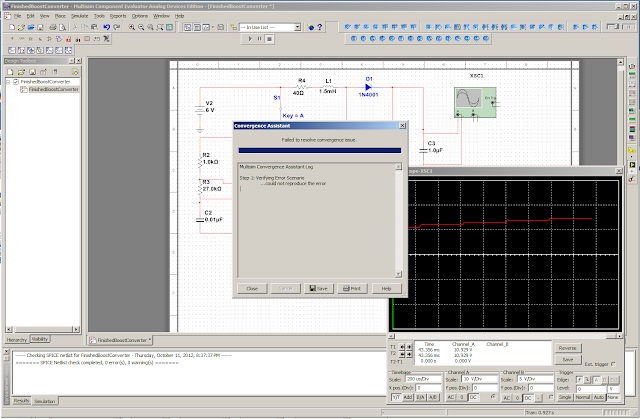
When I tried to simulate it, I ran into a non-descriptive error message. 
Derp
After pressing yes, I got this message. 

Durr Hurr
Despite these issues, I found that the simulator was able to simulate some of the circuit. 

Finished Boost Converter in Multisim
From that occiliscope output you can see the plot converging to about 14.5 V, more than twice the input voltage. 

Conclusion

This circuit can be made fairly inexpensively with off the shelf parts. Such as:
Total: $10.38

The Boost Converter can be used when high voltage is a priority over current, such as charging a capacitor to fire a camera flash, or to power nixie tubes that require high voltages but very little current. 

Monday, August 13, 2012

Javascript Canvas Hack

Last weekend I went to a hackathon in downtown Tucson. Together, with my team, we set out to make a social networking app based around creating and decorating a tile how ever you wanted.

The magic of the idea was that we would have a relevance algorithm that would arrange similar people's tiles together based on what was in the tile.

My job was to create the user interface that would allow users to simply add little stickies to their tile. Below I present the crude result of my 24 hours of effort.


What I made was a Canvas and Javascript hack to basically emulate a windowed graphical user interface. Users can add windows, move them, resize them, add text and delete them. I did this with little understanding of Javascript and no prior experience with canvas. 

You can download my hack. When you download it un-compress the file, inside there will be three files, a .js file, .css file and a .html file. To test it out: open index.html in a web browser.

Saturday, July 21, 2012

Unlock the Supercomputer Hidden in Your PC

Everyone knows computers have been getting faster and have been getting more cores. In 2012, a consumer can buy a CPU with eight cores. However, hidden away in your computer, there may exist dozens or even hundreds of cores you're probably not even using to their fullest potential. They can exist in your Graphics Processing Unit.

In fact, within my laptop, there are fifty cores divided between my CPU and both of its GPUs. Keep in mind my laptop was made in 2009, so more recent computers may have even more, especially if its a desktop or a computer made for gaming.

With all these cores: there is the potential for massive performance boosts in the software we use everyday.

How do you Compare Performance?

Performance can be measured in FLOPSFloating Point Operations Per Second, it's a type of metric used in high performance computing. A floating point number is a decimal number, in binary form, used commonly in scientific and engineering simulations, which utilize a lot of floating point numbers. FLOPS are a very broad metic describing how many times you can manipulate floating point numbers in a second. Operations like comparing two numbers or adding, multiplying, etc. 


GPU vs. CPU
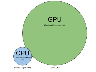
Relative compute performance in relation to size
Because of the increased cores, GPUs can do more FLOPS than a CPU can. In many cases, a good GPU is an order of magnitude faster than a good CPU. That means that while a good CPU might be able to pull a few dozen to about a hundred GigaFLOPS, a good GPU could, theoretically, handle  TeraFLOPS of compute workloads. 

Practical Test

The best GPUs have thousands of cores in them. The Radeon HD 7970 has 2048 programable cores. In contrast: my laptop's best GPU, the GeForce 9600M GT, has just 32 cores. Even still, It's plenty to show off the power of GPUs. 

For a test, I used OpenCL, a parallel programming language that can be used to program CPUs and GPUs alike. I wrote an OpenCL program to compute matrix dot products, between matrices of varying sizes. Computing Matrix dot products are a good way to test performance because they require many computations. Furthermore, they're used in a lot of scientific and graphics calculations. To summarize: in the test, I give the different devices, on my computer, a giant work load, to see how long it takes for them all to finish it.

You can download the source code I made for the test. It is free software, you can use it in your own projects.

Results

Running each of the three OpenCL devices, on my laptop, to compute the dot product between matrices varying from 16x16 to 1024x1024 in size revealed the relative runtimes of each device. 


The red plot is my control, it is a naive, single threaded, implementation of a matrix dot product solver. Unsurprisingly, it took the most time. The violet plot, is the amount of time it took both cores of my CPU to compute the different sized matrices, using my OpenCL code. This was much faster, taking less than half the time. The other two lines, if you can see them, are squished along the x-axis. Both my GPUs took almost no time to compute the matrix dot product. To illustrate this more clearly, I present the last three lines of the outputted data.

Runtimes of computing dot products between nxn matrices on different OpenCL devices
n Single Threaded GeForce 9600M GT GeForce 9400M Core 2 Duo T9600
992 11416.339 ms 22.507 ms 29.262 ms 4256.869 ms
1008 12232.509 ms 23.188 ms 30.678 ms 4754.069 ms
1024 12251.256 ms 24.979 ms 30.846 ms 4464.266 ms

As you can see, while both cores of the CPU combined took nearly 5 seconds to compute a 1024x1024 matrix, A GPU could do it in 30 milliseconds.

In other words, what takes a CPU several seconds, a GPU can do in the blink of an eye.

Limitations

If GPUs are so fast, why haven't they replaced CPUs? The answer is: they're not fast all the time. A matrix dot product is an ideal problem for a GPU because it's a fine grained parallel problem. A Fine grained parallel problem is a problem that can be divided into many small, identical pieces. Such a problem can be easily divided across many cores. Not all problems are like that though. Many problems  have data dependencies between pieces, need to have pieces be solved one at a time, or can't be broken down at all. A GPU can't handel problems like that, but CPUs are exceedingly good at solving them. 

Sunday, July 15, 2012

Home Security Camera

This week I've set my sights on creating a home security camera that can broadcast a live video stream over the Internet!

Setup


I started out with an AMD, 64-bit based, Desktop PC with GNU/Linux Debian Wheezy Testing installed.

I didn't have a webcam, but I did have a MiniDV camcorder that hooked in through the FireWire port, which my computer happened to have a few of.


Lastly, because I was sort of far away from my router, I set up a wireless connection using a USB WiFi adaptor. Driver installation wasn't too bad and my adaptor was compatible with Linux!

Script

To run the transmit script: I made sure to have a full install of GStreamer through my package manager. The script its self was pretty simple and simply took input from the camera, compressed it as a series of JPEG images and sent it out as a TCP stream over port 6000. The IP address my router assigned my streaming computer was 192.168.1.105, this address will vary based on when the router registers a PC. 
#!/bin/bash
gst-launch-0.10 -v dv1394src ! dvdemux ! dvdec ! ffmpegcolorspace ! videoscale ! videorate ! video/x-raw-yuv, height=240, width=427, framerate=3/1 ! jpegenc ! multipartmux ! tcpserversink host=192.168.1.105 port=6000
I stored this script in the file: network-stream.sh and ran the script, in the terminal, using sh network-stream.sh, once I navigated to the directory I stored it in.

Network

Receiving the video over the Local Area Network is very easy. All I really have to do is open VLC on a computer, on the local network, and then type in tcp://192.168.1.105:6000. 

To receive the stream over the internet is a more involved process which requires setting up port forwarding to allow access, for this application, to the Wide Area Network. 

My router's IP address, on the network, is 192.168.1.1. Different routers will have different IP addresses. On the administration page, I set up port forwarding along port 6000 for the TCP protocol. All routers are different, but most will support doing this in one way or another.


Don't forget to set up port forwarding on the modem as well. The process should be similar to setup on the router. Again, you will need to find the network IP address for your modem. Mine was 192.168.0.1. Like with the router, IP address will vary by modem.

Once you have that set up, a user can access your camera through the Internet, all they'll need is the IP address to your house. Unfortunately, most ISPs dynamically assign IP addresses to their customers, the IP address you have will change. If that's the case, you will not be able to access your camera.

The solution to this comes from DNS forwarding services. Basically they can give you an internet domain like my-domain.com. The domain is an alias for your IP address. They will give you a program to run on your computer that updates the IP address your domain is associated with, every time it changes.

In 2012, a decent free DNS forwarding service I've come to use is no-ip.com they haven't yet forced their users to pay for their basic service or only provide a limited time trial. So their service is a good one to use to experiment with servers and web technology if you're not sure you want to invest much money yet.

Testing

Once the DNS forwarding service, network port forwarding and security camera server have been set up: an Internet stream is conceivable. 

If you go into VLC, you can open up the network stream in a very similar maner to opening it up on the LAN, this time you just change the address in VLC: tcp://my-domain.no-ip.org:6000.

You should see the output of the security camera. 


My server has to really crank along to keep up with producing the stream:


The CPU doesn't have too many clock cycles left and the network output, going out at about 100 KiB/s is about as fast as my internet can take. 

Future Work

There are a number of issues with this streaming setup. The most obvious one is the slow frame rate of 3 frames per second. This is a consequence of sending series of JPEG images over the internet, they take about 100 KiB/s to stream. On my internet this is about the upload limit. Faster internet connections can provide a higher frame rate because they can provide more data throughout. 

Another issue is the quality. 240p is barely acceptable. A more appropriate level of definition would be 360p or 480p. 

Both these issues stem from the fact that I'm streaming a JPEG sequence over TCP. First of all, JPEG sequences don't do compression between frames, each frame is individually packaged. This really makes the stream a lot larger that it has to be, especially if the camera is sitting still. A better solution would be to broadcast an actual video stream using codecs like H.264 or VP8. These can provide higher quality and frame rates. I just need to find out how to directly stream these types of formats directly to VLC from GStreamer over the Internet.

Another problem is the use of TCP. TCP is not ideal for live streams because it scales how fast it transmits over the lines of the Internet and guarantees packet transmission. 100% packet transmission is not required for this application. Although TCP is great for transmitting static media over the internet, UDP is better for streaming media because it's designed around sending packets in real time as opposed guaranteeing 100% packet transmission. With TCP, if there's not enough bandwidth for the stream, the stream will become increasingly delayed, with UDP if there isn't enough bandwidth for the stream, packets will be dropped, the image quality will look worse, but it will be in real time. The only problem with UDP is that it doesn't scale like TCP does. ISPs can't make UDP take less bandwidth, like TCP, because all it does is throw out packets. As a result, some ISPs do not allow home internet users the ability to broadcast UDP streams. They can't control it. So in this, initial attempt, I used TCP, even though I'd like to have a UDP stream working. 

Tuesday, July 3, 2012

Creating a Particle Collision Simulator

I've decided to create a particle collision simulator durring this summer as a pet coding project to hone my C programming skills.

My hope is to, eventually, have a system that can simulate thermo-dynamic systems ranging from airfoils to sterling engines. But first I need to get the basics down and be able to detect particle collisions and recalculate particle velocities and positions.

Below: a description of the theoretical underpinnings of particle collision detection.

You can check up on the project at the google code page I created.


Thursday, June 21, 2012

WiFi at One Kilometer

Introduction

Today I tried an experiment to see how far I could get useable WiFi signals. I made something called a cantenna, which is a type of home made directional antenna. I also used an external WiFi adaptor with a removable SMA antenna jack (so I could hook my antenna into it).

Pictured are my two main peripherals, on the left was the cantenna I made out of a Bushes Baked Beans can. I designed it based on some very useful instructions on turnpoint.net. On the right is my wireless adaptor. It's the engenius wireless 11n, fortunetly it uses the rtl8188su chipset, which has drivers for Linux. 

Setup

Of course, when doing this experiment, I wanted to ensure that I could get the best reception possible. 

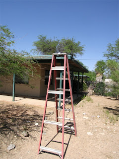
Pictured above, my router sits on top of a ladder in the front of my yard. This was to make sure that I had as close to line of sight as I could get. My router isn't anything special, just a Rosewill n150 WiFi router. 

For my set up in the field, I carried with me my laptop, a table and my peripherals.

Experiment

In this experiment I observed ping times and packet losses, from pining the router, at five locations from the router. I used both the omni-direction high gain antenna that came with the adaptor and the cantenna I made to compare their ping times.

Location 1

Location 1 was 587 feet away from the router.

The ping output using the omni-direction antenna was:
16 packets transmitted, 16 received, 0% packet loss, time 15016ms
rtt min/avg/max/mdev = 0.815/3.236/19.571/4.490 ms
No packet loss (which is good).

The ping output using the cantenna was:
16 packets transmitted, 15 received, 6% packet loss, time 15030ms
rtt min/avg/max/mdev = 0.921/4.787/41.169/9.755 ms
Ouch, a packet loss. So early in the game and already the directional antenna is doing worse than the omni-directional one.

Location 2

Location 2 was 1,365 feet away from the router.

The ping output using the omni-direction antenna was:
17 packets transmitted, 16 received, 5% packet loss, time 16032ms
rtt min/avg/max/mdev = 2.249/9.219/49.795/11.473 ms
Looks like the omni-directional lost a packet this time.

The ping output using the cantenna was:
17 packets transmitted, 17 received, 0% packet loss, time 16025ms
rtt min/avg/max/mdev = 1.340/3.313/15.711/3.280 ms
Looks like the cantenna is doing better no packet loss, its average response time is also about three times lower too. Maybe location 1 was just a slight hickup.

 Location 3

Location 3 was 1,987 feet away from the router.

The ping output using the omni-direction antenna was:
17 packets transmitted, 15 received, 11% packet loss, time 16021ms
rtt min/avg/max/mdev = 1.547/13.897/41.956/12.821 ms
That's much more significant packet loss than before, response time is also up by about 4 milliseconds too.

 The ping output using the cantenna was:

17 packets transmitted, 17 received, 0% packet loss, time 16026ms
rtt min/avg/max/mdev = 1.520/12.951/71.046/16.841 ms
No packet loss, and average response time is a bit quicker than the omni-directional antenna.

Location 4

Location 4 was 2,968 feet away from the router. 

At this point, I was unable to use the omni-directional antenna to get a signal. Its max ranges seems to be between two and three thousand feet. 

But the cantenna still worked. 

The ping output using the cantenna was:
17 packets transmitted, 16 received, 5% packet loss, time 16031ms
rtt min/avg/max/mdev = 3.760/15.199/48.870/12.584 ms
Not too bad for over a half mile. At this distance I was still able to stream 360p youtube videos. Look at the output of the network history graph.

Location 5

Location 5 was 3289 feet away from the router.

This seems to be the last place I was able to get a signal of any sort. I was on top of a hill for this one (which was the only place where I could get a line of sight path to the router at this point).

The ping output using the cantenna was:
16 packets transmitted, 16 received, 0% packet loss, time 15023ms
rtt min/avg/max/mdev = 3.523/12.998/44.225/11.653 ms
This was a kilometer away from the router. I don't think this is too bad. I would have tried to go out further and see if I could find another hill or ridge to get on top of, but by this point I was tired of walking in the desert. I'll save extended range tests for another day.

Conclusion

I was able to attain a usable WiFi signal, a kilometer away from a router, using either commercially available products or home made equipment that can be acquired for under $100.

I'm sure I could push the range even further in the right environment. 1 kilometer was the furthest distance I could get a dependable line of sight connection. As long as you can achieve a line of sight path between the receiver and the router, who knows how far you can achieve reception?

High range line of sight WiFi has many applications. It can be used in highly dispersed computer networks over large desolate areas where a conventional wired network would be unfeasible. I'm also intrigued with the possibility of using this for something like remote controlled aircraft. The range should be sufficient for a small model aircraft, and if enough bandwidth can be procured you could even do things like provide a live 720p video stream from the aircraft or provide what ever kind of sensor data you can think of.

Wednesday, June 20, 2012

Porting Data Sanctuary

A friend of mine recently released a top down shooter called Data Sanctuary. Although the only playable file he made was a Windows binary, he also released the source code. I spent part of my day using it to port it over to Mac.


You can download the Mac version of the game here. Be careful when you're playing it, things can quickly get tense if you're not careful.

Note: Make sure you have a decent graphics card or you will have very choppy frame rates.